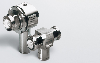
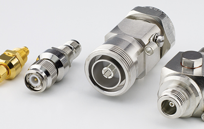
Coax
EMP Protection
Coaxial Surge Suppressors
There are two different functional designs:
-
- – Quarter Wavelength Shorting Stub – with or without DC pass
- – Surge suppressors with Gas Discharge Tube
Coaxial Surge Suppressors
There are two different functional designs:

These surge suppressors act like narrow bandpass filters. Only a narrow bandwidth is allowed to pass; other frequencies are shorted and discharged to ground. The design of these surge suppressors involves a direct and solid short-circuit between the centre and outer conductor of the coaxial device.
This short-circuit path, in the form of a coaxial line and of a precisely defined length, is designed to have an electrical length equivalent to one quarter wavelength (λ/4) of the signal frequency to be transmitted. As an alternating voltage of the correct frequency passes along the quarterwavelength shorting stub it experiences a 90° phase angle rotation, is then reflected totally at the short (180° phase angle rotation) and finally travels back along the quarter wavelength stub (= a futher phase angle rotation of 90°).
This represents a total phase angle rotation of 360°. The reflected signal and the incident signal are in phase and the operating signal does not see the short.
It is, therefore, not affected by it. However, if an alternating voltage of a different frequency is present, then these special factors are not given and the energy is short-circuited (= discharged to ground).

The method of operation of this device can be likened in principle to an electrical switch which, when a certain
voltage (d.c. sparkover voltage) is reached, switches the inner conductor to ground.
The design of this device consists of a Gas Discharge Tube installed directly between the inner and outer conductors of a coaxial line. When a higher voltage than the impulse sparkover voltage (=overvoltage)
appears on the line, the Gas Discharge Tube will fire and, depending on the prevalent energy, a glow discharge of between 75-90 V (current in milliampere range) or ionisation with an arc voltage of 10-20 V (currents ranging from amps to kiloamps) takes place. When the energy subsides (= is converted to heat), the discharge extinguishes itself automatically. After a cooling-down period of 30 secs., the Gas Discharge Tube is fully operational again. After several very high discharge currents occurring within a few seconds of each other, the functionality of the device may be impaired. It is recommended, therefore, that the gas capsules are replaced at certain intervals.